HR-IM-P Housing Rings - HR-IM-P-19

Product Description
Axially Assembled, Internal, ANSI Metric
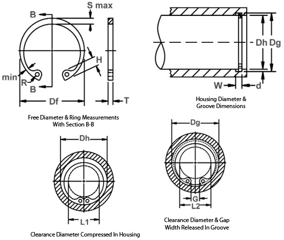
Once installed in the groove of a housing/bore, the portion of the ring protruding from the groove (also called a “shoulder”) holds an assembly in place.
*F.I.M. (Full Indicator Movement) – Maximum allowable deviation of concentricity between groove and shaft.
For plated rings, add 0.05 to the listed maximum thickness. Maximum thickness will be a minimum of 0.005 less than the listed groove width (W) minimum.
| Housing Dia. (Ds In.) | Housing Dia. (Ds mm) | Groove Dia. (Dg and Tol.) | Groove Width (W and Tol.) | Ring Free Dia. (Df and Tol.) | Ring Thickness (T and Tol.) | Groove Dia. (F.I.M.*) | Wt. Per 1000 pcs. | Released In Groove (L2) | Compressed in Housing (L1) |
|---|---|---|---|---|---|---|---|---|---|
| 0.748 | 19 | 20.1 (+0.15) | 1 (+0.15) | 21.1 (+0.25/-0.13) | 0.9 (±0.06) | 0.1 | 0.59 | 12.5 | 11.4 |