HR-IM Shaft Rings - HR-IM-510

Product Description
Axially Assembled, Internal, Metric
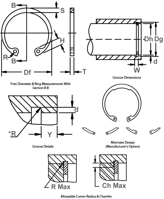
Once installed in the groove of a housing/bore, the portion of the ring protruding from the groove (also called a “shoulder”) holds an assembly in place.
*The radius "R" on the load side must not exceed 0.1T.
| Housing Dia. (mm) | Ring Thickness (T and Tol.) | Groove Dia. (Tg and Tol) | Groove Width (W Min) | Groove Depth (d) | Ring Free Diameter (Df and Tol) | Edge Margin (Y Min) | Thrust Load Ring (Pr kN) | Thrust Load Groove (Pg kN) | R/Ch Max | Max Load w/R/Ch Max. (P'r kN) |
|---|---|---|---|---|---|---|---|---|---|---|
| 510 | 8 (-0.15) | 524 (+1) | 8.2 | 7 | 535 (+3/-1.5) | 21 | 1894 | 1894 | 7 | 156 |