SR-EM-F Shaft Rings - SR-EM-F-4

Product Description
Axially Assembled, External, ANSI Metric
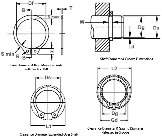
Once installed in the groove of a shaft, the portion of the ring protruding from the groove (also called a “shoulder”) holds an assembly in place.
*F.I.M. (Full Indicator Movement) – Maximum allowable deviation of concentricity between groove and shaft.
Sizes 4 through 6 standard material – carbon steel; optional material – beryllium copper.
For plated rings, add 0.05 to the listed maximum thickness (T) and believed end thickness (U) values.
| Shaft Dia. (mm) Ds | Shaft Dia. (In.) Ds | Groove Depth (d) | Groove Dia. (Dg and Tol.) | Groove Width (W and Tol.) | Ring Free Dia. (Df and Tol.) | Ring Thickness (T and Tol.) | Groove Dia. (F.I.M.*) | Wt. Per 1000 pcs. | Expanded Over Shaft (L1) | Released In Groove (L2) |
|---|---|---|---|---|---|---|---|---|---|---|
| 4 | 0.157 | 0.1 | 3.8 (-0.08) | 0.32 (+0.05) | 3.6 (+0.05/-0.1) | 0.25 (±0.05) | 0.03 | 0.017 | 7 | 6.8 |